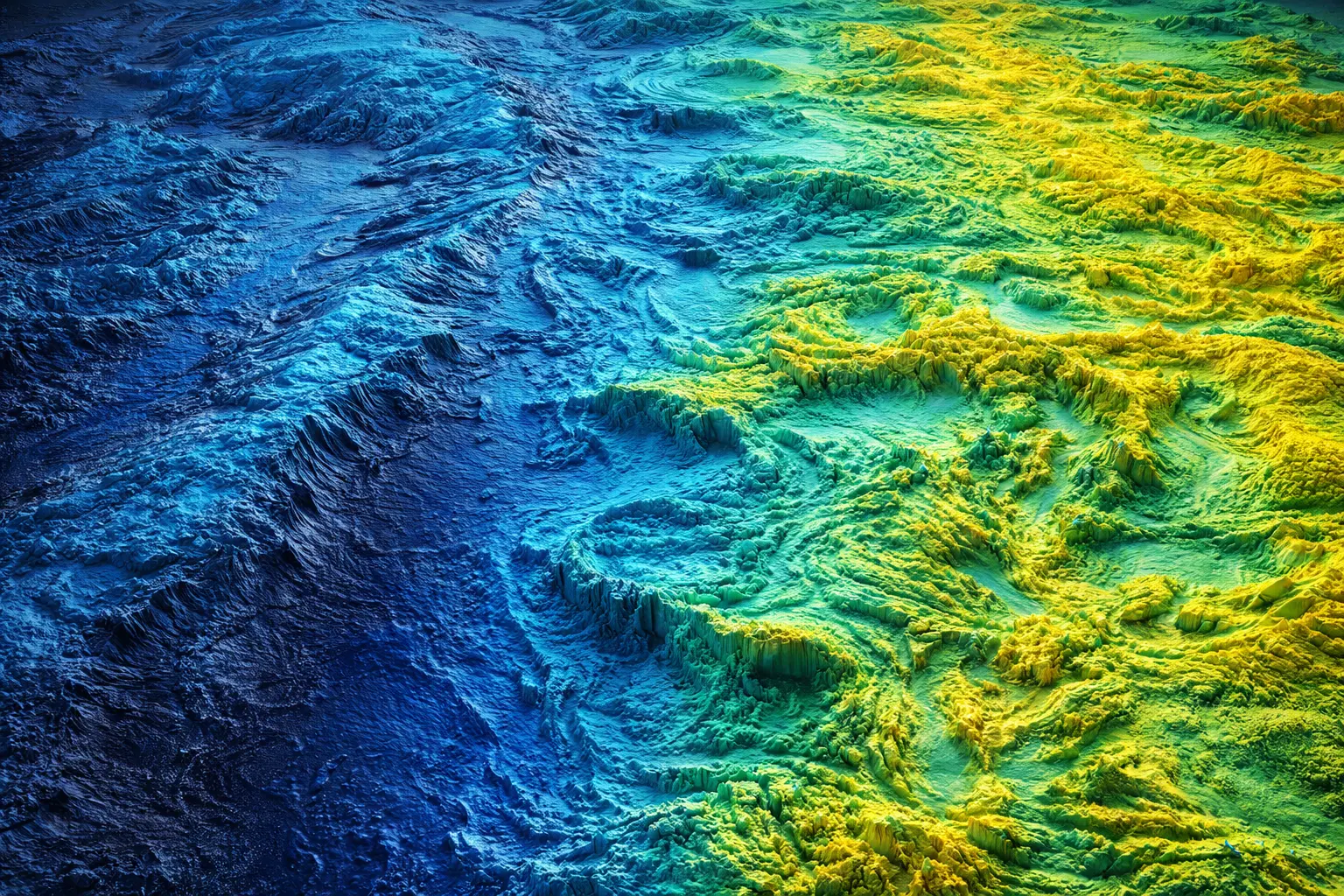
Bathymetric LiDAR and Sonar Mapping
How deep is this coastal water? What does the river bottom look like? Bathymetric LiDAR uses green laser (532 nm) penetrating clear water, while sonar uses acoustic pulses for deeper/turbid water. This model derives water column correction, implements multibeam sonar geometry, and maps underwater topography for navigation, habitat, and hazard assessment.
Prerequisites: underwater acoustics, light attenuation, sonar ranging, refraction
1. The Question
What’s the depth and bottom topography of this shallow coastal bay?
Two technologies for underwater elevation:
Bathymetric LiDAR (ALB - Airborne Lidar Bathymetry):
- Green laser (532 nm) penetrates water
- Measures from aircraft
- Shallow water (<50m, clear conditions)
- Simultaneous topography (infrared) + bathymetry (green)
Sonar (Sound Navigation and Ranging):
- Acoustic pulses (10-500 kHz)
- Boat/ship-mounted or autonomous underwater vehicles
- Deep water (thousands of meters)
- Works in turbid water
Applications:
- Nautical chart production
- Coastal hazard assessment (tsunami inundation)
- Habitat mapping (coral reefs, seagrass)
- Dredging and navigation
- Underwater archaeology
- River bathymetry
- Reservoir volume calculation
2. The Conceptual Model
Bathymetric LiDAR
Dual-wavelength system:
Infrared (1064 nm):
- Reflects off water surface
- Measures water surface elevation
Green (532 nm):
- Penetrates water column
- Reflects off bottom
- Return delayed by water travel time
Water column correction:
\[d_{\text{water}} = \frac{c_{\text{air}} t_{\text{total}} - c_{\text{water}} t_{\text{water}}}{2}\]More precisely:
\[z_{\text{bottom}} = z_{\text{surface}} - \frac{c_{\text{water}}}{2} (t_{\text{green}} - t_{\text{IR}})\]Where:
- $c_{\text{water}} = c_{\text{air}}/n$ (n = refractive index ≈ 1.33)
- Speed of light in water: ~2.25 × 10⁸ m/s
Limitations:
Turbidity (Secchi depth):
Beer’s Law attenuation:
\[I(z) = I_0 e^{-Kz}\]Where:
- $K$ = attenuation coefficient (m⁻¹)
- Typical: K = 0.05-0.5 m⁻¹
Maximum depth:
Approximately 2-3 × Secchi depth.
Clear water: 40-50 m
Turbid water: 5-10 m
Very turbid: No penetration
Multibeam Sonar
Principle:
Transmit acoustic pulse, receive echoes from multiple angles simultaneously.
Sound speed in water:
\[c = 1449 + 4.6T - 0.055T^2 + 0.00029T^3 + 1.34(S - 35) + 0.016z\]Where:
- $c$ = sound speed (m/s)
- $T$ = temperature (°C)
- $S$ = salinity (PSU)
- $z$ = depth (m)
Typical: c ≈ 1500 m/s (much slower than light!)
Two-way travel time:
\[d = \frac{ct}{2}\]Multibeam geometry:
- Transducer array spans ~120-150° swath
- Simultaneously measures depth at 100s of points
- Swath width: ~3-4 × water depth
Example: 100m depth → 300-400m swath width
Refraction Correction
Snell’s Law at water surface:
\[n_1 \sin\theta_1 = n_2 \sin\theta_2\]For air ($n_1 = 1$) to water ($n_2 = 1.33$):
\[\sin\theta_{\text{water}} = \frac{\sin\theta_{\text{air}}}{1.33}\]Off-nadir beams refract toward normal.
Effect: Horizontal position shifts inward.
Correction essential for accurate positioning.
3. Building the Mathematical Model
Bathymetric LiDAR Depth Calculation
Surface return time: $t_{\text{IR}}$
Bottom return time: $t_{\text{green}}$
Water travel time:
\[\Delta t = t_{\text{green}} - t_{\text{IR}}\]Depth below surface:
\[d = \frac{c_{\text{water}} \Delta t}{2} = \frac{c_{\text{air}} \Delta t}{2n}\]Where $n = 1.33$ (refractive index of water).
Example:
$\Delta t = 200$ ns
\[d = \frac{3 \times 10^8 \times 200 \times 10^{-9}}{2 \times 1.33} = \frac{60}{2.66} = 22.6 \text{ m}\]Total elevation:
\[z_{\text{bottom}} = z_{\text{surface}} - d\]Turbidity Limitation
Signal-to-noise ratio:
\[SNR = \frac{I_{\text{bottom}}}{I_{\text{noise}}}\]Bottom return intensity:
\[I_{\text{bottom}} = I_0 R_{\text{bottom}} e^{-2Kd}\]Where:
- $R_{\text{bottom}}$ = bottom reflectance (~0.1-0.4)
- Factor of 2: Down and back through water column
Detection threshold: SNR > 3 (minimum)
Maximum depth:
\[d_{\max} = \frac{\ln(I_0 R_{\text{bottom}} / I_{\text{threshold}})}{2K}\]Example: $K = 0.1$ m⁻¹ (moderate clarity)
\[d_{\max} \approx \frac{\ln(1000)}{0.2} = \frac{6.9}{0.2} = 34.5 \text{ m}\]Multibeam Positioning
Range to bottom:
\[R = \frac{ct}{2}\]Beam angle: $\theta$ (from vertical)
Horizontal offset:
\[x = R \sin\theta\]Vertical depth:
\[z = R \cos\theta\]Sound speed correction:
If $c$ varies with depth (common):
Ray tracing through water column needed.
\[\frac{dx}{dz} = \frac{\sin\theta}{\cos\theta} = \tan\theta\]With $\theta(z)$ from Snell’s Law:
\[c(z) \sin\theta(z) = c_0 \sin\theta_0\]Iterative solution required for accurate positioning.
Swath Coverage
Swath width:
For flat bottom at depth $D$, beam angle $\pm \theta_{\max}$:
\[W = 2D \tan\theta_{\max}\]Example: $D = 100$ m, $\theta_{\max} = 60°$
\[W = 2(100) \tan(60°) = 200 \times 1.73 = 346 \text{ m}\]Survey efficiency:
Line spacing = swath width → 100% coverage
Tighter spacing → overlap for quality assurance
4. Worked Example by Hand
Problem: Calculate bathymetric LiDAR depth measurement.
Data:
- Water surface elevation: $z_{\text{surface}} = 2.5$ m (above datum)
- Infrared return time: $t_{\text{IR}} = 1000$ ns (round-trip to surface)
- Green return time: $t_{\text{green}} = 1400$ ns (round-trip to bottom)
- Refractive index: $n = 1.33$
Calculate bottom elevation.
Solution
Step 1: Water column travel time
\[\Delta t = t_{\text{green}} - t_{\text{IR}} = 1400 - 1000 = 400 \text{ ns}\]Step 2: Speed of light in water
\[c_{\text{water}} = \frac{c_{\text{air}}}{n} = \frac{3 \times 10^8}{1.33} = 2.26 \times 10^8 \text{ m/s}\]Step 3: Water depth
\[d = \frac{c_{\text{water}} \Delta t}{2} = \frac{2.26 \times 10^8 \times 400 \times 10^{-9}}{2}\] \[= \frac{90.4}{2} = 45.2 \text{ m}\]Step 4: Bottom elevation
\[z_{\text{bottom}} = z_{\text{surface}} - d = 2.5 - 45.2 = -42.7 \text{ m}\](Negative: below datum)
Summary:
- Water depth: 45.2 m
- Bottom elevation: -42.7 m (relative to datum)
Note: This is near maximum depth for bathymetric LiDAR in clear water.
5. Computational Implementation
Below is an interactive bathymetric mapping simulator.
Max measurable depth: -- m
Swath width: -- m
Points measured: --
Mean depth: -- m
Observations:
- Blue area represents water column
- Brown area shows measured seafloor
- Orange dotted line marks maximum measurable depth
- LiDAR limited by water clarity (turbidity)
- Sonar works in deep/turbid water but from vessel
- Clear water (high Secchi) enables deeper LiDAR penetration
- Bright bottoms (sand) return stronger signal than dark (mud)
- Data gaps occur where depth exceeds technology limits
Key findings:
- Bathymetric LiDAR optimal for shallow clear water (<50m)
- Sonar required for deep or turbid conditions
- Water clarity and bottom reflectance control maximum LiDAR depth
- Complementary technologies cover full range of conditions
6. Interpretation
Coastal Zone Mapping
NOAA bathymetric LiDAR program:
Systematic coastal mapping for:
- Nautical chart updates
- Tsunami inundation modelling
- Habitat assessment
- Emergency response
Example - Hurricane Sandy (2012):
Post-storm bathymetric LiDAR:
- Documented massive sediment redistribution
- Inlet breaches
- Dune erosion
- Critical for recovery planning
Coral Reef Mapping
Challenges:
Complex 3D structure at fine spatial scale.
LiDAR advantages:
- Complete coverage (vs. transects)
- Rugosity measurement (surface complexity)
- Change detection (growth, bleaching, storm damage)
Example - Florida Keys:
Repeated surveys detect:
- Coral decline
- Algal overgrowth
- Storm impacts
Management application:
Prioritize restoration sites, track recovery.
River Bathymetry
Traditional surveys:
Boat-based sonar in navigable reaches only.
Bathymetric LiDAR:
Maps entire river including:
- Shallow riffles (boats can’t access)
- Bank-to-bank coverage
- Floodplain + channel in one dataset
Applications:
- Salmon habitat (pool-riffle structure)
- Flood modelling (channel capacity)
- Sediment transport (bedform mapping)
Archaeological Applications
Underwater sites:
Shipwrecks, submerged settlements, harbor structures.
LiDAR detection:
Subtle features on seafloor visible in high-resolution bathymetry.
Example - Submerged prehistoric landscapes:
8000-year-old settlement sites now offshore mapped with bathymetric LiDAR.
7. What Could Go Wrong?
Suspended Sediment
Backscatter from water column:
Sediment particles reflect laser/acoustic signal.
LiDAR: False bottom returns from turbid layers.
Sonar: Reduced penetration, noise.
Worst case: Impossible to detect true bottom.
Solution:
- Post-processing filters
- Survey during low-turbidity conditions
- Combined interpretation with water column imagery
Surface Waves
Rough sea state:
Water surface moves during measurement.
LiDAR error: ±0.5-1m in moderate waves.
Sonar: Motion compensation systems on vessel.
Solution:
- Survey in calm conditions
- Average multiple measurements
- Motion reference unit (MRU) on aircraft
Refraction Uncertainty
LiDAR off-nadir beams:
Snell’s Law correction requires knowing:
- Beam angle
- Water surface orientation
- Refractive index (varies with salinity, temperature)
Uncertainty propagates to horizontal position.
Solution:
- Minimize scan angle
- Measure water properties
- Cross-line overlap for validation
Bottom Classification
Sonar backscatter varies with:
- Grain size (sand vs. mud)
- Roughness
- Biology (seagrass, coral)
Challenge: Distinguishing features from noise.
Solution:
- Backscatter mosaics
- Ground-truth sampling
- Multi-frequency analysis
8. Extension: Side-Scan Sonar
Different technology: Measures backscatter, not just bathymetry.
Geometry:
Transducers aimed sideways (perpendicular to track).
Creates acoustic image of seafloor.
Applications:
- Object detection (shipwrecks, boulders, debris)
- Seafloor classification (sediment type, bedforms)
- Pipeline/cable inspection
- Search and recovery
Advantages:
- High-resolution imagery (cm-scale)
- Wide swath coverage
Disadvantages:
- Doesn’t directly measure depth
- Geometric distortion
- Interpretation requires expertise
Often combined with multibeam sonar:
- Bathymetry from multibeam
- Texture from side-scan
- Comprehensive seafloor characterization
9. Math Refresher: Wave Attenuation
Beer-Lambert Law
Exponential decay:
\[I(z) = I_0 e^{-\alpha z}\]Where:
- $I(z)$ = intensity at depth $z$
- $I_0$ = incident intensity
- $\alpha$ = attenuation coefficient (m⁻¹)
Applicable to both light and sound in water.
Attenuation Coefficient
Light:
\[\alpha_{\text{light}} = \alpha_{\text{absorption}} + \alpha_{\text{scattering}}\]Dominated by:
- Pure water absorption (increases with wavelength)
- Chlorophyll absorption (green algae)
- Suspended sediment scattering
Sound:
\[\alpha_{\text{sound}} = \alpha_0 f^2\]Where $f$ = frequency.
Higher frequency → more attenuation → shorter range
Trade-off: Resolution vs range.
Two-Way Attenuation
Laser/sonar pulse travels:
- Down to bottom: attenuated by $e^{-\alpha z}$
- Back to sensor: attenuated again by $e^{-\alpha z}$
Total: $I_{\text{return}} = I_0 R e^{-2\alpha z}$
Factor of 2 in exponent critical for range calculations.
Summary
- Bathymetric LiDAR uses green laser (532 nm) penetrating clear water to ~50m depth
- Dual-wavelength measurement separates water surface from bottom returns
- Water column correction accounts for slower light speed and refraction in water
- Turbidity limits LiDAR depth via exponential attenuation following Beer’s Law
- Multibeam sonar uses acoustic ranging for deep or turbid water mapping
- Sound speed variation with temperature/salinity requires ray tracing for accuracy
- Swath width typically 3-4× water depth for multibeam systems
- Applications span coastal mapping, coral reef monitoring, river surveys, archaeology
- Challenges include suspended sediment, surface waves, and refraction correction
- Complementary technologies cover full range from shallow clear to deep turbid water
- Critical for navigation safety, habitat assessment, and hazard modelling